Homework 4A
What’s due
- HDL: As with prior assignments, your completed HDL needs to be submitted (via GitHub) to Gradescope. A significant portion of the grade comes from passing unit tests.
- Questions: The GitHub submission needs to include completed answer to the questions in
questions.mdin the repo. - Demo: An in-person demo is required for part of the grade. The demo needs to be completed during office hours (instructor or TA hours) within 10 days after the assignment is officially due. Normally this would put the deadline on March 11th, which is during spring break. The “workday count” is suspended during break. Consequently, the demos on this assignment must be completed by the end of Thursday, March 19th. Late penalties are based on the Gradescope submission, not the completion of the demo.
Demos!
Most/all remaining assignments will require an in-person demonstration (and answering some questions) within 10 days of the due date to get full credit. Demos must be done during office hours. Review the office hour schedule for sessions that may work well with your schedule.
Setup
Create a Repo
- Navigate to link
- If shown a list of IDs, select your WUSTL Key from the list (this only needs to be done once. If you already did this during studio, you won’t be given the optiona gain)
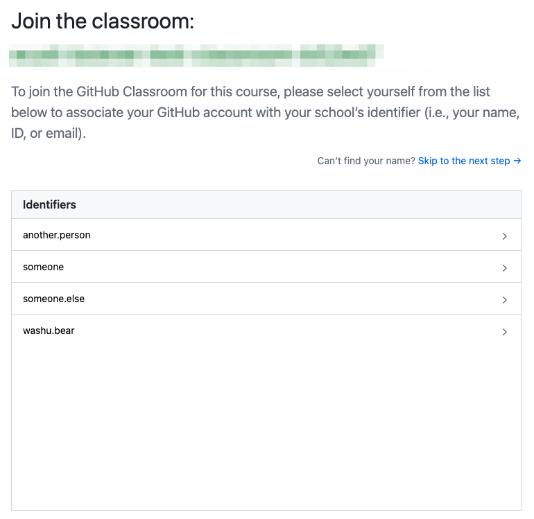
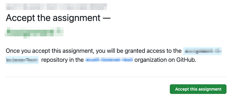
- “Accept the assignment”.
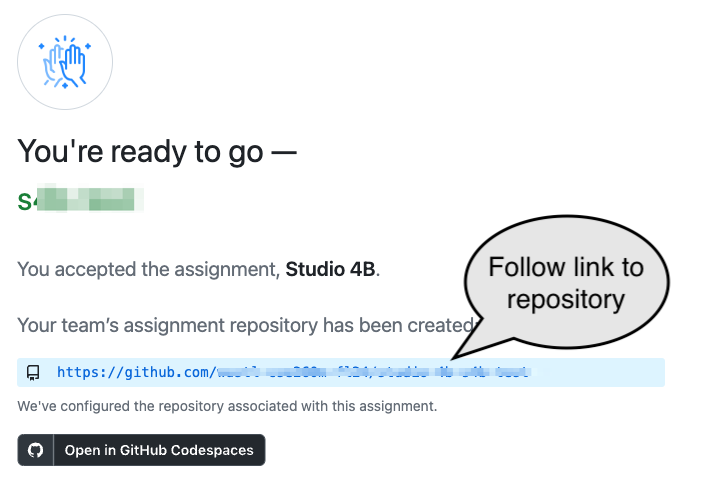
-
Follow the link to the new repository for the group:
Setup Caution!
The first time you do this you may be told that there is a
Repository Access Issue. This is often because you have been “invited” to join our class organization and haven’t yet accepted the invitation. Either:- Check the email address associated with your GitHub account — you should have an email with an offer to join the course’s organization or
- Update the Update/use this URL to view and accept the invitation. Be sure to change the “GITHUBUSER” part of the URL to your username: https://github.com/WashU-CSE2600-SP26/homework-4a-GITHUBUSER/invitations (E.g., if your GitHub username were washubear, the URL you’d use would be https://github.com/WashU-CSE2600-SP26/homework-4a-washubear/invitations)
Codespaces
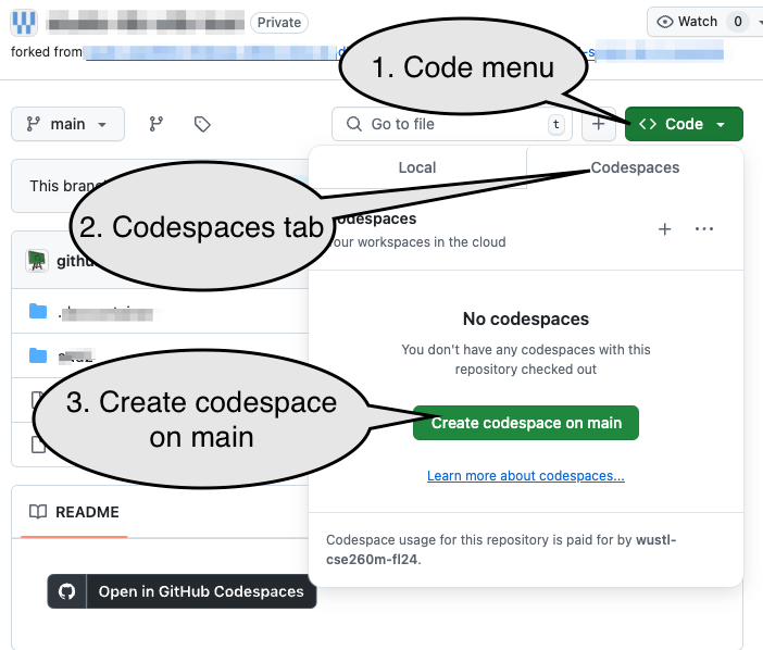
- We’ll be using Codespaces for many studios and assignments.
- Create a code space from the repository:
Beware!
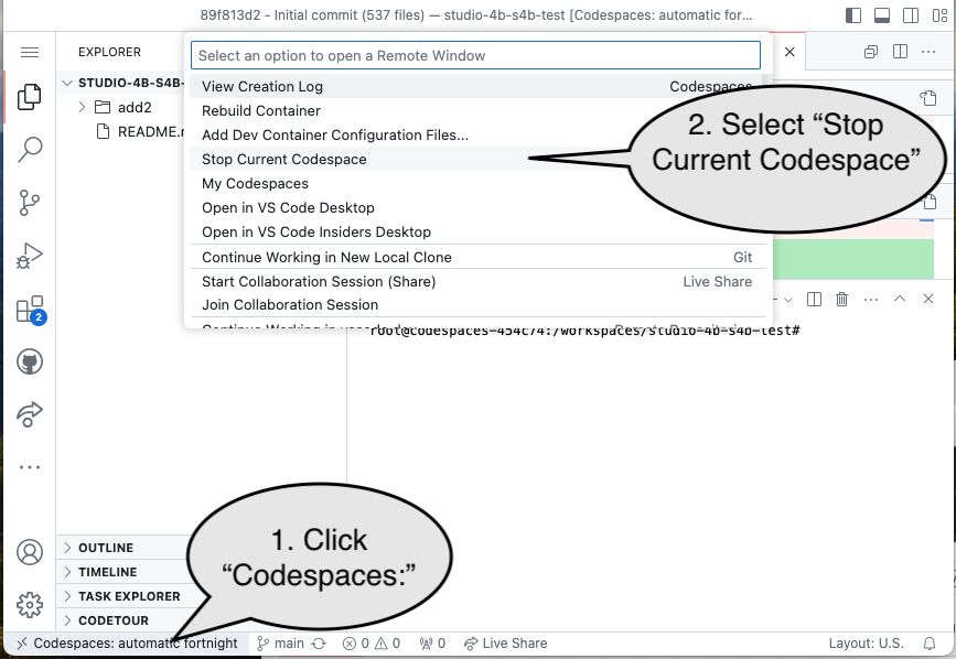
The Codespace typically takes about 2-4 minutes to set up. If you stop working for more than a minute, please explicitly stop the Codespace (see the bottom of this assignment). You can restart the codespace by simply going to https://github.com/codespaces and clicking on the name of the Codespace for the repository. (The page will have a list of codespaces, the number of Cores and RAM for each, etc.)
Alternatives to Codespaces
There are two alternatives to the web-based Codespace:
- Use a local installation of VS Code to connect to the Codespace. See: Local VS Code Connection to Codespace.
- Run everything entirely locally, which will allow you to work without an internet connection and may be faster, but it may require more than a gigabyte of space. See: Running Entirely Locally
Problem 1: Your assignment: Simple Combinational Logic
-
Run the
1.1 simple_comb testbench verificationtask (Click the VSCode Tasks icon on the side bar ( ) and then the task’s name). Observe that the
 PROBLEMStab shows that several test cases failed: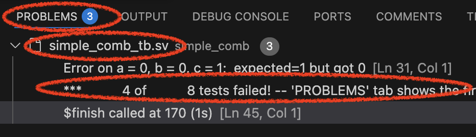
-
The “Vaporview” pane will allow you to explore signals that were being used in the test. You will need to
Add signals from the Netlist View(the wires / variables in the HDL) and will probably want to always enableAuto Reload.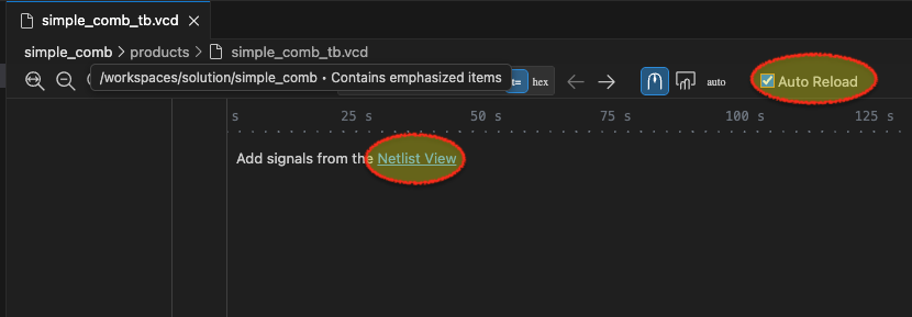
Expand the
simple_comb_tb(this is the test bench), then thedut(the “device under test”), then select variablesa,b, andc: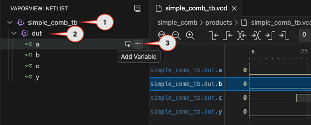
-
Notice the picture above only shows the initial values of
a,b, andcbut you should be able to see the full signal (zoom to fit, or zoom in/out, or scroll). If you click the mouse along the signal it will show you the values of each at exactly that instant. Or if you click and drag you can see how they change as time changes. Review them from the beginning (t=0) to the end (t=175). -
Run the
0.0 Edit questions.mdtask and answer question 1 in the designated place (don’t remove the# Qlines!, but remove/replace theTODOlines. You can answer with plain text, although you are also welcome to use MarkDown notation for styling if you’d like). -
Run the
1.2 Edit simple_comb.svtask. Review the description of what’s expected and fix the designated line using basic Verilog operations (behavioral Verilog with symbols for the operations, like&for AND). -
Re-run
1.1 simple_comb testbench verificationand confirm that all tests pass in thePROBLEMSpane. (Or, if not, continue to editsimple_comb.sv). -
Once it correctly passes the test bench, run ask
1.3 Simulate simple_comb.sv, which will allow you to simulate the circuit. Be sure to hit the "play" button in theDIGITALJS: CONTROL` pane to simulate the circuit.Caution!
This “gate level” simulation does not consistently refresh the view if/when you update the underlying code. Be sure to close this form of simulation before re-running it!
-
Set
cto a 1 and bothaandbto 0. -
Complete
Q2inquestions.md. -
The “synthesis” takes our HDL description and breaks it down into simpler parts which can be run on real hardware. Run task
1.4 AIG Mapping. CompleteQ3andQ4inquestions.md. If the results look like empty, You may have to pan/scroll around to see the graph generated by the AIG mapping.
Problem 2: Verilog Structure
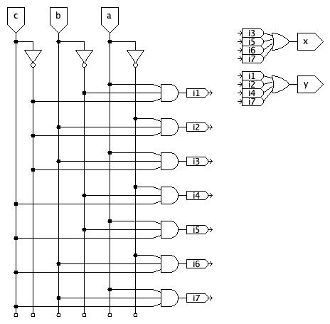
Consider the circuit:
-
Use task
2.1 Edit structural.svand complete the HDL description using structural modeling!Primitive gates can be modeled with the format:
type(output, inputs...). For example, a 3-inputorgate could be modeled withor(output, a, b, c);or with a unique name for the instance of theorgate, likeor gate1(out, a, b, c);.Beware!
For most of the semester we will use SystemVerilog’s
logictype, which can represent either a connection between elements or a value stored (latched or in a flip-flop). There are cases, including here, where awiretype needs to be used to represent a true wire.The simulator for the test bench is very strict about this and will require the output of primitive, structural gates be an appropriate type, like
wire.The simple simulator is much less rigid. It makes some assumptions about default behavior and will simulate things that are not defined precisely enough for the simulator.
The difference in behavior between different tools is partly a result of their different intended uses and partly a result of how rigidly they enforce standards.
Caution!
The problem asks for a structural model. You should not use
always_combstatements.assignshould only be used for the final, simple assignments of outputs (of the formatassign output = internal. They should not use more complex expressions.) You should use the primitive partsand(...),or(...),not(...), etc. Although you may pass test cases with other forms of modeling, credit will only be given for a structural model. -
Use the
2.2 Simulate structural.svtask and the2.5 structural testbenchtasks to test your work. Revise your work until you pass the testbench (but, again, be sure you are using ONLY structural elements. No use of operators like~,^,&, etc.) -
Run task 2.4 (
AIG Mapping) and 2.5 (iCE40 Mapping) and answerQ5inquestions.md.
Problem 3: Basic addition - Revisiting Hw 2a
Consider adding 2-digit binary numbers, $a$ and $b$ to produce the 2-bit result, $s$ and a one-bit carry-out, $c$:
Caution!
Note that a, b, and s are each two-bit binary values (rather than each being made of two, distinct, binary inputs). Moreover, you should assume that values are “most significant bit first” unless otherwise specified.
- Use task 3.1 to edit
add2.sv. Complete it as described. Use tasks 3.2 and 3.3 to test your work. Update it until you pass all tests.- Task
3.2 Simulate add2.svwill allow you to simulate the adder. The inputs and outputs are no longer simple, binary value. Hovering over an input or output will allow you to use the base being used to enter or show that value:
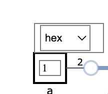
Caution!
You must update values and then click out of the input box for the simulator to use the updated value. (If the cursor is still in the box, it isn’t clear that you are done typing a new value)
- Task
3.3 add2 testbench verificationwill allow you to run a comprehensive testbench against the adder. Make sure your adder passes the tests.
- Task
-
Use the
3.4 add2 AIG Mappingand3.5 add2 iCE40 Mappingto get a sense of how your approach is represented in individual logic operations vs. how it will use the iCE40 logic blocks, which are like small look-up tables (LUTs) that can be used to implement a variety of simple logic operations. - Use
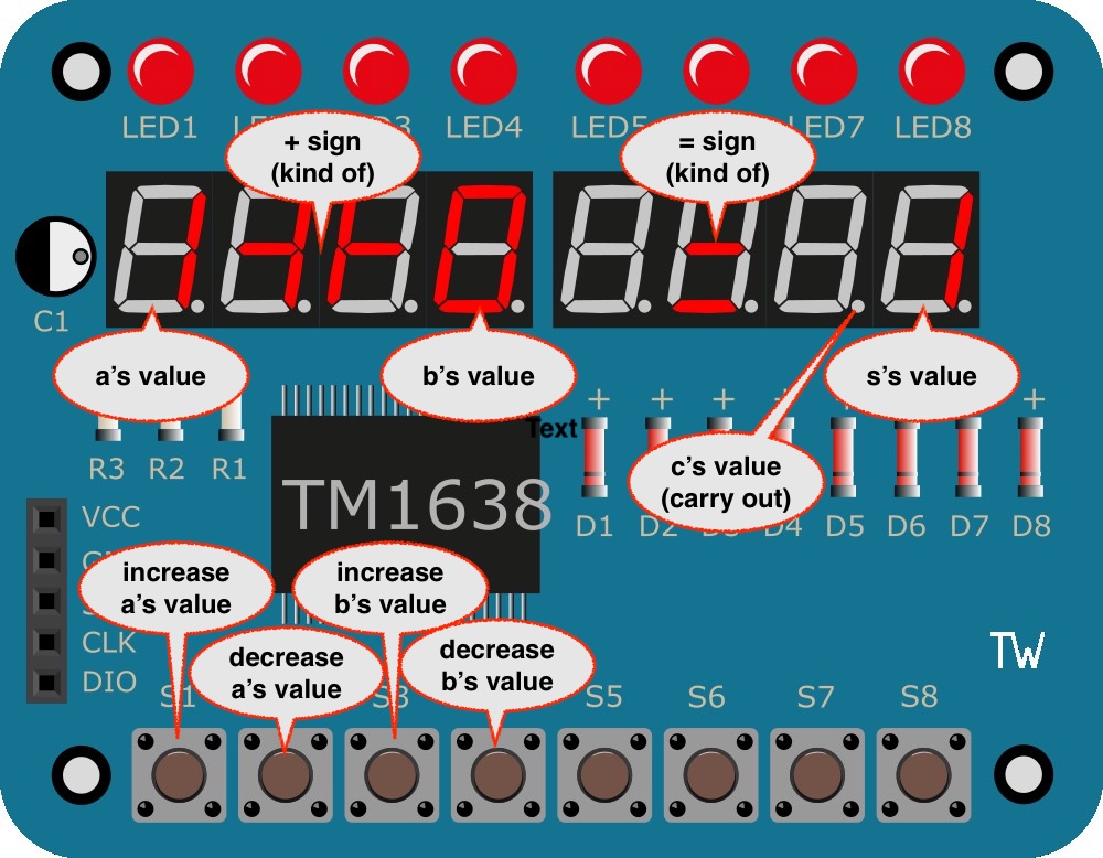
3.6 add2 iCE40 bitstreamto create a bit stream and Program your Device. (This requires running theFPGA Image Servertask first. TheFPGA Image Serverwill continue to run until you hit it’s task again to end it. Leave it running.)- The left four buttons can be used to increase or decrease the values used for
aandb, which are displayed in the designaed aresa. -
s, the sum, will be shown on the rightmost digit. -
c, the carry out, will be shown on the decimal point of the second digit from the right.
- The left four buttons can be used to increase or decrease the values used for
-
Use the
3.7 iCE40 Routing(This requires that theFPGA Servertask is running and will open a new webpage. It may also take some time to run). This can give to get a sense of what resources are used for your adder and the interface to the external hardware. Expand the sections and try to identify the percentage of logic cells (LCs) being used. You can useOpen Imageto browse a large picture of how the blocks inside the iCE40 are being used and connected for this project. It’s a large grid of blocks and you may have to pan/scroll to find blocks that are being used, which have red-shaded lines. -
Complete
Q7-Q13inquestions.md
End of work
Caution!
Be sure to “stop” your Codespace. You have approximately 60 hours of Codespace time per month. Codespaces often run for ~15 minutes extra if tabs are just closed.
Submission
The assignment will be submitted via GitHub and Gradescope.
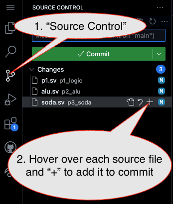
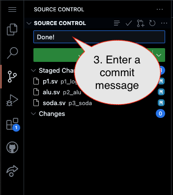
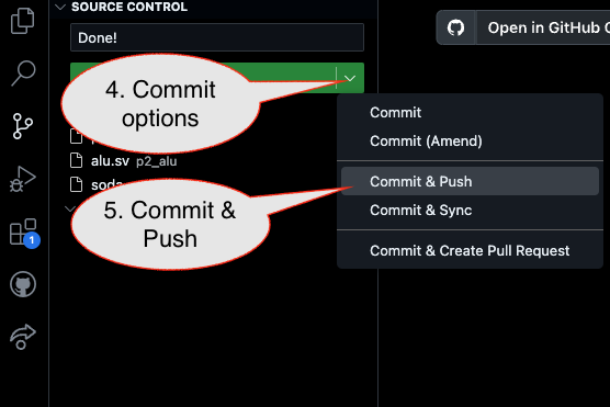
1. First, be sure to commit and push files to GitHub (as shown in studio).
Caution!
Be sure all files are included, including completed questions.md, which is 30% of the grade!!!
1.1
1.2
1.3
2. Then go to GitHub.com and confirm the updates are on GitHub
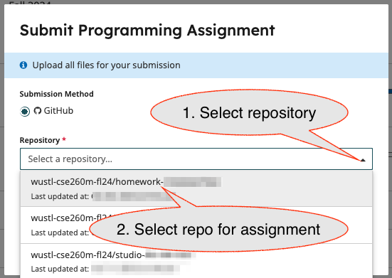
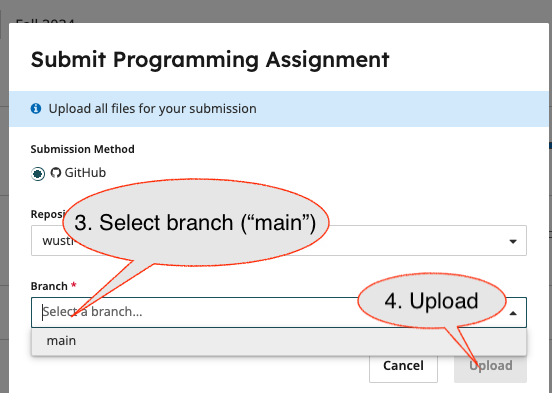
3. Finally (after confirming updates are on GitHub), go to the assignment in Gradescope and import it from GitHub:
3.1
3.2
- Submission Link: Gradescope